Main Home page 로 이동 바랍니다 www.aeft.co.kr
1-1. 열 교환기 실험장치(Heat Exchanger System)
2. Blower Performance Tester(송풍기 실험장치)
4. Air Compressor Tester(공기 압축기 실험장치)
5. M.T.E Apparatus(운동량 정리 실험장치)
9. Thermal Conductivity Experimental Apparatus(열전도율 실험장치)
10. Multi Component Loadcell System(다점분력 검출기)
11. Hot Wire Probe/Pitot Tube/Anemometer Calibrator(풍속 교정기)
12. 계측용 장비
-. Multi Manometer
-. Multi Pressure Scanning System
-. LDV
-. PIV
-. High Speed Camera
-. Turn Table
풍동은 유체 실험에서는 기초 장비이며, 금세기 Software 의 발전으로 전산유체(CFD)를 이용해서
실험을 대신하는 경향이 있었으나 그것또한 실험으로 얻어진 Data를 이용해야 하는 이유로
풍동은 기계, 항공, 우주, 조선, 건축, 토목등 유체에 관련된기초 실험에 꼭 필요한 장비로 인식되어
지고 있습니다.
풍동은 사용목적, 풍속의 크기, 시험부의 크기, 설치장소 및 조건, 계측기기류 들을 고려하여 선택해
야 합니다.
풍동은 형태에 따라
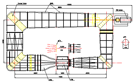
▶순환형(Close Type, Gottingen Type)

|
HS-CWT45 |
HS-CWT60 |
HS-CW-90 |
Test Section |
450x450x1000mm |
600x600x1500mm |
900x900x3600mm |
Velocity Range |
1-60m/s |
1-60m/s |
1-50m/s |
Uniformity |
1.5% at 1-10m/s 1.0% at 10-50m/s |
||
Stability |
+/- 1%/min |
||
Turbulence |
under 1% at 1-10 m/s, under 0.4% at 10-50m/s |
||
Blower |
Axial Fan |
Axial Fan |
Axial Fan |
Motor |
15Kw |
40Kw |
50Kw |
Speed Controller |
Inverter Control |
Inverter Contro |
Inverter Contro |
Optional Acce. |
Hot Wire anemometer, Scaivalve, Micromanometer,Smoke Generator, Pressure Sensor , Pitot Tube, 3-6 Component Balance, Traverse unt, Turn Table, Control Software, Etc |
||
▶토출형(OpenType)
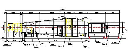
|
HS-OWT30 |
HS-OW50 |
Test Section |
300x300x1000mm |
500x500x1000mm |
Velocity Range |
1-30m/s |
1-30m/s |
Stability |
±1.5% at 1-5m/s, ±1% at 5-30m/s |
|
Blower |
Turbo |
Turbo |
Volume |
180 CMM |
600 CMM |
Motor |
5.5Kw |
22Kw |
Velocity Control |
Inverter |
Inverter |
Power |
AC 200 3phase, 60Hz |
|
Accessories |
Pitot Tube, Multi-manometer, Inclined Manomenter Aerofoil,& Cylindrical Model with pressure hole |
|
Optionl Acce. |
Hot Wire anemometer,Scaivalve,Micromanometer Smoke Generator, Pressure Sensor , Pitot Tube 3-6 Component Balance, Traverse unt, Turn Table Control Software, Etc. |
|
▶흡입형 풍동(Suction Type)
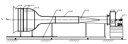
|
HS-SWT30 |
HS-SW50 |
Test Section |
300x300x1000mm |
500x500x1000mm |
Velocity Range |
1-25m/s |
1-25m/s |
Stability |
±1.5% at 1-5m/s, ±1% at 5-30m/s |
|
Blower |
Turbo or Axial |
Turbo or Axial |
Volume |
120 CMM |
410CMM |
Motor |
4Kw |
15Kw |
Velocity Control |
Inverter |
Inverter |
Power |
AC 200 3phase, 60Hz |
|
Accessories |
Pitot Tube, Multi-manometer, Inclined Manomenter Aerofoil,& Cylindrical Model with pressure hole |
|
Optionl Acce. |
Hot Wire anemometer,Scaivalve,Micromanometer Smoke Generator, Pressure Sensor , Pitot Tube 3-6 Component Balance, Traverse unt, Turn Table Control Software, Etc. |
|
< 상위메뉴>←여기를 클릭하세요
2. Blower Performance Tester(송풍기 실험장치)
펜, 송풍기 실험 장치는 가종 펜, 송풍기의 풍량, 압력, 회전수, 소비전력 등을 측정하여
시험 송풍기의 효율 및 성능을 검사하여 공조 설계시 Duct 의 크기 및 길이등을 설계할수 있는
기초 자료가 되며, 학생들로 하여금 Blower 의 특성을 이용한 공조 설계를 할수 있게 할수 있음.
|
HS-BPT25 |
HS-BPT35 |
Blower Type |
Turbo Fan |
Turbo Fan |
Flow Rate |
26CMM |
32CMM |
Static Pressure |
150mmH2O |
150 mmH2O |
Motor |
2.2Kw |
2.2Kw |
Air Duct |
250 Acryl or PVC |
350A Acryl or PVC |
Air Flow Control |
Inverter |
Inverter |
Power |
AC 200 3phase, 60Hz |
|
Accessories |
Pitot Tube, Orifice, Nozzle |
|
Optionl Acce. |
Anemometer, rpm Sensor, Power Meter |
|
3. Air Flow Tester(공역학 실험장치)
이장치는 Orifice 및 Venturi를 이용하여 공기 유량등을 유체역학 계산에의한 값과 측정된 유량과 비교 또는 Report 작성등 수업등을 진행할수 있습니다.
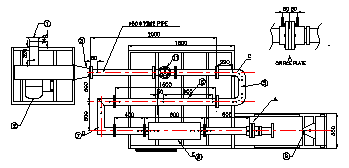
4. Air Compressor Tester(공기 압축기 실험장치)
이 장치는 산업용 공기 압축기의 유량, 압력,소비전력, 압축시간,등을 측정하여 압축기의 성능검사 및 원리등을 공부할수 있는 장치입니다.
|
HS-ACT75 |
HS-ACT220 |
Compressor Type |
Air-Cooled recipprocating machines |
|
Diameter x Stroke x Number |
65mm x 37mm x 1 |
65mm x 56mm x 2 |
Discharged Pressure |
Max. 9.9Kg/Cm2 |
Max. 9.9Kg/Cm2 |
Discharged Air Flow Rate |
0.14CMM |
0.372 CMM |
Drive Motor |
1 Hp |
2.2Kw |
rpm |
1170 |
1020 |
Accessories |
Manometer, Orifice, Thermometer,Pressure Gauge Power Meter |
|
< 상위메뉴>←여기를 클릭하세요
5. M.T.E Apparatus(운동량 정리 실험장치)
Specification
-. Dimension : 1500 x 600 x 700 mm
-. Air Tank : Diameter 300mm x 500mm High
-. Orifice : Diameter 10mm
-. Nozzle : 3 ea.
-. Pressure : 10Kg/Cm2 (Digital Display)
-. Traverse : 1 ea. Manual type
-. Manomter : 500 mmH2O
-. Air regulator : 20Kg/cm2
-. Model : 2 ea.
-. Option : Air compressor(3 Hp)
이장치는 풍동실헝이나 제한된 공간속에서의 유체 유동 현상을 가시화 할수 있는 장치입니다.
연기의 성질은 어느정도 점도가 있어서 공기중에서 쉽게 확산되지 말아야 하며 또한 실험자의
안전을 위하여 인체에 해가 없어야 합니다.
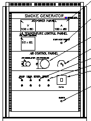
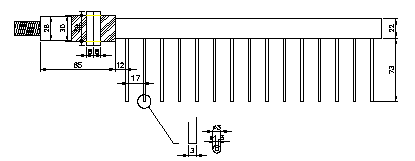
Smoke Generator 본체 Smoke Generator Probe
Specification:
-. Smoke Capacity : 10 liter/min.
-. Pressure : 0.1- 0.5Kg/Cm2
-. Oil Reservoir : App. 200cc
-. Smoke Nozzle : 1.5mm x 20, P=20mm
-. Power : AC 220Vac, 60 Hz
-. Flow Control : 12A needle Valve
< 상위메뉴>←여기를 클릭하세요
이장치는 각종 Probe 또는 Sensor 등을 측정 부위로 정밀 이송하기 위한 장비입니다.
그용도에 따라 1,2,3,4차원으로 나눌수 있으며, 구동 Motor와 Controller 에 따라서
나누기도 합니다 또한 Computer를 이용한 Program 제어 가 가능하며, 수동으로 제작도
가능합니다.
Specification |
Auto Traverse |
Manual Traverse |
채널용 |
X axia |
300, 500, 1000mm |
300, 500, 1000mm |
1300, 2000mm |
Y axia |
300, 500, 1000mm |
300, 500, 1000mm |
500, 500mm |
Z axia |
300, 500, 1000mm |
300, 500. 1000mm |
400, 400mm |
Resolution |
±0.1 mm |
±0.1 mm |
±0.1mm |
Motor |
Stepping Motor |
none |
Stepping Motor |
Rotation |
option 360Deg. |
||
Mechanical Sys. |
Ballscrew, LM Guide, Limite switch |
||
Specification
-. Nozzle Material : Duralumin
-. Nozzle Size : Diameter 25mm
-. Fan : 2 CMM
-. Air Tank : 1000(W) x 400(D) x 600(H)mm
-. Traversing Range : 1000mm
-. Thermometer : 0 to 50℃
-. Pitot Tube Diameter : 6 mm
-. Manometer : 600mmH20
-. Accessories : Standard Acce.
9. Thermal Conductivity Experimental Apparatus(열전도율 실험장치)
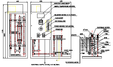
Specification
-. Insulated Chamber : Glass wool
-. Standard disk : Dia. 40mm Copper
-. Test Disk : Dia. 40mm stainless steel
-. Head Tank : 200 x 300 x 150 mm
-. Immersion Heater : 500W
-. Water Flow rate : 100 liter/min
-. Thermo Detector : T-type Probe
-. Multi Scanning Selector Switch: 12 points
-. Digital Thermometer(Panel mounted)
Option :
Data Acquisition Box with Software
< 상위메뉴>←여기를 클릭하세요
10. Multi Component Loadcell System(다점분력 검출기)
|
|||||||||||||||||||||||||||||||||||||||||||||||||||||||||||||||||||||||||||||||||||||||||||||||||||||||||||||||||||||||||||||||||||||||||||
< 상위메뉴>←여기를 클릭하세요
11. Hot Wire Probe/Pitot Tube/Anemometer Calibrator(풍속 교정기)
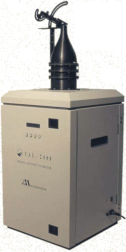
CAL-2000
DIGITAL AIR SPEED CALIBRATOR
The CAL-2000 unit features a uniform flow rate, with low turbulence level. Its large output cross-section (1.95 sq. Inches) allows calibration of almost any standard sensor. The probe angles can be adjusted easily by two manual controls.
The CAL-2000 is a complete stand-alone system. It does not require any pressure inlets or external sources for generating the requested air speed. Its "Micronel" filter provides clean air flow without any dust or moisture particles which might attach to the sensor and change its calibration curve. The flow range configuration is done by entering a plate to a slot inside the noise filter section.
Features
Stand-Alone System.
Turnkey System.
RS-232 Serial Interface.
High Accuracy to 0.5% of Reading.
Velocity Controller maintains highly stable Air Speed Velocity.
Environmental monitoring:
- Barometric pressure,
- Humidity,
- Differential pressure,
- Temperature.
Calibration curve (with LDA) Supplied with each system.Applications
Calibration of hot-wire and hot-film sensors.
In-situ calibration.
Software
The CAL-2000 system is supplied with a setup and control software for PC compatible computers. All system setups can be controlled remotely via that software. The system also interfaces with "LIN-FLOW" software for calibration of Hot-Wire sensors with the AN-2000 software. The system may also be operated from any computer (PC, Vax, Macintosh, Sun etc.) which contains a serial port (RS-232C standard), by sending simple ASCII commands.

Specifications
Flow Rate: 1 to 70 m/sec.
Accuracy: 0.5% of reading.
Temperature range: 0 to 50 deg. C.
Humidity: 0 - 90% RH
Power Requirement:
230 Vac +/- 10% (115V models available).
Power consumption: 650W at full
speed.
Weight:69.5 Kg.
< 상위메뉴>←여기를 클릭하세요
AEFT 엡트텍
e-mail : airforce71@yahoo.co.kr
homepage : www.aeft.co.kr